Geophysics
Methods and Applicability
Geophysical and geological researches on land and water.
METHODS APPLIED:
- Electrometry through vertical electrical surveys (SEV) or induced resistivity and polarization profiling, natural potential.
- Obtaining 2D and 3D images of the structure of the basement.
- Continuous resistivity profiles on water.
The resistivity method is the main geoelectric method currently used in geophysical practice. It consists of investigating the interdependence between the subsoil structure and the subsoil resistivity distribution, measured at the surface. It is based on the existence of resistivity contrasts between different rocks and geological formations that participate in the geological composition of an area.
The resistivity ρ is measured in the field with an AMNB quadripole array consisting of an AB transmission line through which a current of intensity İ is introduced into the ground through two emission electrodes A, B and an MN reception line measuring the potential difference ΔV created between electrodes M, N at the crossing of current through the resistance represented by the subsoil. The four electrodes are 1 cm thick stainless steel rods inserted 10-15 cm into the soil, and the connection between them and the measuring device is made by electric cables, so the method is totally non-invasive and can be applied to any type of ground. At present, terrestrial measurements mostly use passive multielectrod cables, with electrodes contacts at equal distances, which are suitable for automatic measurements. A switch box assigns successively to each electrode the emission or reception function according to a command file created depending on the type and characteristics of the measuring array.
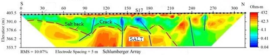
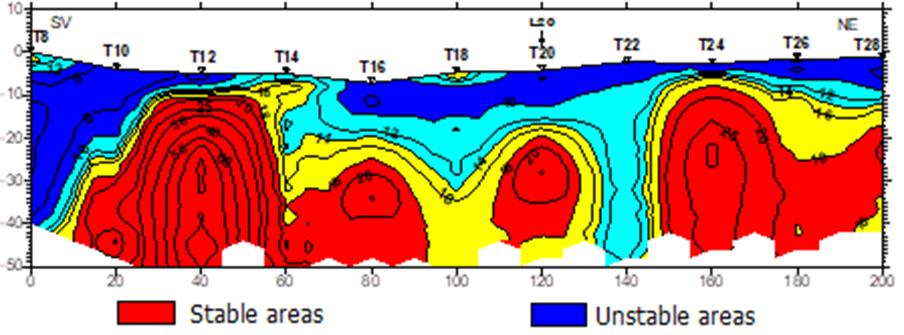
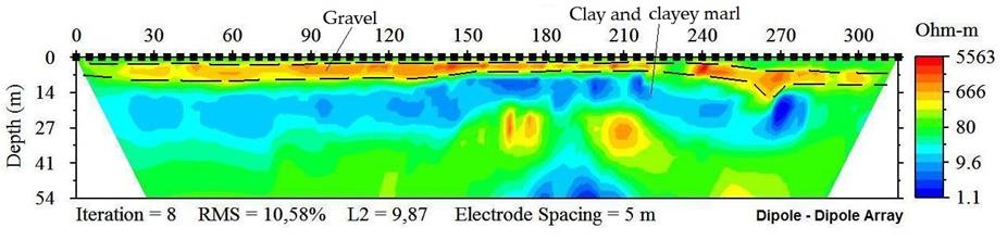
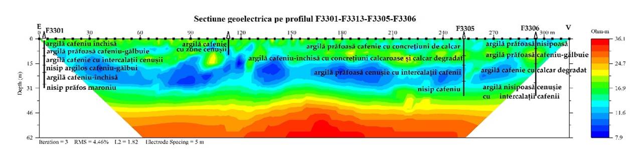
The results are represented as vertical sections of resistivity, which show the distribution of this parameter in the direction and in depth, in direct correlation with the geological structure of the subsoil up to a maximum depth that depends on the spacing between the electrodes, usually ten times the spacing between them in the case of automatic measurements using multielectrode cables, or one fifth of the maximum length of the transmission line for manual cable measurements.
The geological interpretation of the resistivity sections is based on the information available about the researched area - technical, geological, geophysical, geochemical and weather data, information from the authorities and locals.
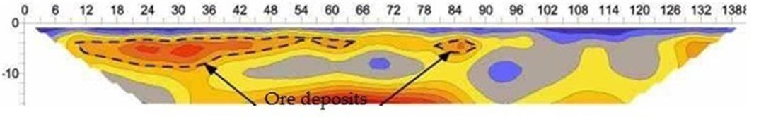
The applicability of the resistivity method is related to the existence of a resistivity contrast between the target object and the adjacent environment, the contrast being determined by preliminary measurements or estimated on the basis of information about the work area or similar areas. At the same time, it is necessary that the object to be pursued should have a minimum size of half the distance between the reception electrodes and be at a depth comparable to its size.
Existence in the immediate vicinity of the earthing of some equipments operating in DC may affect the quality of the measurements.
PRACTICAL APLICATIONS